Source: Thermal Control Circle
EMG Electric Door Adjustment Method
h1>
2.iMatic fully intelligent LCD series debugging
1 Operation and display
General:
– Graphic display
– Complete the operation by using the keys
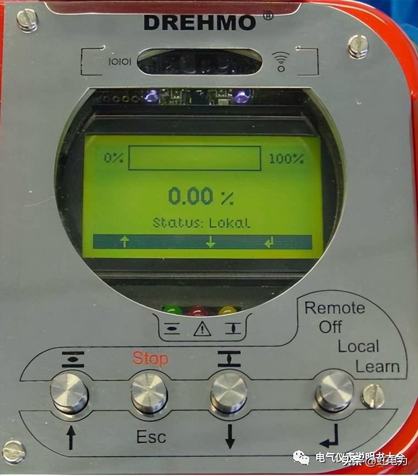
1.1 display
After booting, the LCD screen displays the following screen:

![]()
Also all three field lights turned on should flash for approximately 3 seconds.
![]()
Button 1— Previous menu prev. selection – increase value increase value
Button 2— Cancel – return back
Button 3 – next menu next selection – decrease the value decrease valu
Button 4–Enter select select Nextnext
3. Executor debugging
3.1 Briefly operate the \”,¯\” button and observe whether the valve position display is consistent with the operating direction. If it is inconsistent: go to the menu
Learn mode >Parameters>Power supply>Phase correction will display the default power connection sequence of the current actuator. Please select another connection sequence under the current menu. Example: If the actuator currently defaults to CW (clockwise direction), please select CCW (counterclockwise direction).
3.2 Briefly operate the \”,¯\” button to determine whether the rotation direction of the actuator output shaft is consistent with the valve opening direction. If they are inconsistent, please select from the following menu: Learn mode>Parameters>Valve>Closing direction
Select the corresponding items CW (clockwise), CCW (counterclockwise).
When the selection is changed, the actuator will have a fault alarm (red light on), please proceed to step 3.3.1.
3.3 Open and close position stroke setting:
3.3.1 Clear the factory stroke (the factory stroke range is set to 90 laps)
Select under the menu Learn mode >Learn mode>change final positions clear position close the item and press the \”Enter\” button to confirm.
General advice: Clear all the fully closed and fully open positions before resetting them.
3.3.2 Set the full off position
After clearing the original stroke, operate the \”¯\” button under the menu Learn mode>Learn mode>change final positions>set position closed to run the actuator to the fully closed position., press the \”Enter\” button to confirm. The closing stroke position setting is completed.
3.3.3 Follow steps 3.3.2 to complete the fully open position setting.
3.4 Opening torque setting
Under the Learn mode>Parameters>valve>Tripping Torque opened menu Enter the actual required value.
3.5 Shutdown mode setting
In the Learn mode>Parameters>valve>Switching off mode) menu Select below:
Stop position (limit shutdown), pos.-close/Md-open (limit close/open torque), Md-close/Pos.-open (torque close/limit open), Md-close/Md-open (torque off).
3.6 Dead Zone Settings
In Learn Enter the actual required value under the mode>Parameters>Process>Accuracy.Xp menu, range (0.5%-5%)
3.7 When the regulating type (005) is changed to the switch type (003).
In Learn mode >Parameters>Process>Change Enabled to Disabled under the positioner menu
本站内容及图片来自网络,版权归原作者所有,内容仅供读者参考,不承担相关法律责任,如有侵犯请联系我们:609448834
