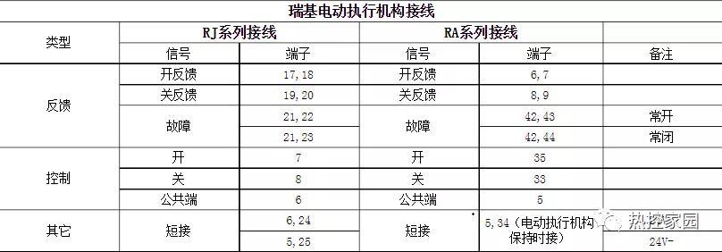
The following is the wiring method of the electric door
![]()
During analog control, command: 26+27-, feedback: 22+23-, 4 and 41, 5 and 39 short circuit.
- This actuator has a dedicated remote setting device for setting modifications Valve parameters, the layout of the valve screen has areas I, II, and III. I area is the valve position display area, which displays the current valve position value in real time in the form of valve opening percentage. Area II is the work setting area or status alarm area, starting with the character \”F\” or \”A\”. Area III is the working parameter setting value display area or battery display area.
- Mode selection knob (red button) is placed In the \”stop\” position, aim the setter at the display screen, press any key on the setter (excluding the reset key), and the \”H-01\” screen will appear in area II on the display; use the down key to make the following characters appear in area II. : H01—Close direction selection(The numbers 0 (clockwise) and 1 (counterclockwise) will appear in area III of the submenu)
H02—Remote Preferences(O (close priority), 1 (open priority) numbers will appear in area III of the submenu)
H03—In-place control options(The numbers 0 (jog) and 1 (hold) will appear in area III of the submenu)
H04—Close limit protection option (submenuIII area will have 0 (unprotected), 1 (protected) numbers)
H05—Close over-torque protection value selection (submenuZone III will display the current valve closing torque value)
H06—Open over-torque protection value selection (submenuArea III will display the current valve opening torque value)
H07—ESD selection (0 will appear in the emergency operation III area (execution off action), 1 (perform opening action) or 2 (no action) number)
H08—Close limit point confirmation item (confirm to close limit)
H09—Open the limit point confirmation item (confirm to open the limit)
H10—Current torque display item (set whether the screen displays the torque value)
Set the above parameters through the setter
3. The following is a Chinese comparison of the alarm code: (1) F-01 (Instruction error) (2) F-02 (ROM error) (3) F-03 (RAM error) (4) F-04 (A/D error) (5) F-05 (reset limit) (6) F-06 (torque overload) (7) F-07 (memory error) (8) F—08 (valve position overflow) (9) F—09 (valve position underflow) (10) F—10 (counting overflow) (11) F—11 (valve closing over-torque) (12) F—12 (Valve opening excessive torque) (13) F —13 (power supply phase loss) (14) F — 14 (motor overheating) (15) F — 15 (motor stall) 16) F — 16 (power outage) (17) F — 17 (wrong direction) (18) F— 18 (ESD closes the valve) (19) F—19 (ESD opens the valve) (20) F—20 (ESD is valid) (21) F—21 (subtraction error) (22) F—22 (addition error) ( twenty three)A-01 (Instructions are normal) (24) A-02 (ROM is normal) (25) A-03 (RAM is normal) (26) A-04 (A/D is normal)
4. The following are common faults and solutions:
1. Analysis of common fault causes of power supply phase loss and troubleshooting methods. There are two types of power supply phase loss of actuator: static phase loss and dynamic phase loss. A quick way to distinguish between these two types of phase loss is: in local mode, turn the operating button (black button) in the on or off direction. If the display immediately displays a \”power phase loss\” alarm, it is a static phase loss; if If the \”power phase loss\” alarm appears on the display after 1-2 seconds, it is a dynamic phase loss; there are differences in the cause analysis and troubleshooting methods for the two types of phase loss.
1.1 Analysis and troubleshooting of common fault causes of static phase loss Method
1.1.1 Cause analysis 1: One phase of the three-phase power supply of the actuator is missing.
Troubleshooting method 1: Use an electric pen or multimeter to measure whether the voltage on the power terminal of the actuator is normal. If not, check whether the user\’s power distribution system and lines are working normally. If there is a fault, the user needs to eliminate it to ensure that the power supply is normal.
1.1.2 Cause analysis 2: The control circuit board signal connection is unreliable.
Troubleshooting method 2: Reconnect the signal cable or replace it with a new one.
1.1.3 Cause Analysis 3: Circuit components related to the power board are damaged.
Troubleshooting method 3: Replace the power board with the same model.
1.2 Analysis and troubleshooting methods of common faults of dynamic phase loss:
1.2.1 Cause analysis 1 :Control lineThe circuit board signal connection is unreliable.
Troubleshooting method 1: Reconnect the signal cable or replace it with a new one.
1.2.2 Cause analysis 2: The AC contactor of the actuator is damaged.
Troubleshooting method 2: Replace the AC contactor with the same model.
1.2.3 Cause analysis 3: The motor of the actuator is damaged.
Troubleshooting method 3: Replace the motor with the same model.
1.2.4 Cause analysis 4: The circuit components related to the power board are damaged.
Troubleshooting method 4: Replace the power board with the same model.
2. Analysis and troubleshooting methods of common faults of motor stall2.1 Cause analysis 1: The manual/electric switching device is locked and the motor idling. Troubleshooting method 1: Use the setter to reset the actuator, turn the handwheel of the actuator, and then The electric operation actuator can be switched to electric mode and can run continuously; if it cannot be switched to electric mode, it is necessary to repeat the previous steps several times. If the fault is still not solved, please contact the manufacturer.
2.2 Cause analysis 2: The AC contactor controlling the motor is damaged or the sowing head on the main control board is loose.
Troubleshooting method 2: Replace the damaged AC contactor or re-insert the plug-in on the main control board.
3. Analysis and troubleshooting methods of common power failure causes
3.1 Cause analysis 1: The user\’s power fuse is burned out.
Troubleshooting method 1: The user checks the corresponding power distribution system and eliminates the fault.
3.2 Cause Analysis 2: Anti-wave on the power boardThe surge power fuse is damaged.
Troubleshooting method 2: Replace the anti-surge power fuse of the same model.
3.3 Cause Analysis 3: The power transformer of the actuator is damaged.
Troubleshooting method 3: Replace the power transformer with the same model if it is damaged.
3.4 Cause Analysis 4: The control circuit board signal connection is unreliable.
Troubleshooting method 4: Reconnect the signal cable or replace it with a new one.
4. Analysis and troubleshooting methods for common causes of motor overheating
4.1 Cause analysis 1: If the motor runs continuously for a long time and the temperature exceeds 130°C, the temperature switch automatically disconnects for protection.
Troubleshooting method 1: The actuator suspends work and can resume work only after the motor temperature drops.
5. Analysis and troubleshooting methods of common valve closing over-torque faults
5.1 Cause analysis 1: The actuator closing over-torque protection parameter setting is too small.
Troubleshooting method 1: Use the setter to reset the shutdown torque protection value (increase it), and perform electric operation in local mode
mechanism, so that it can run back and forth for 2 to 3 full strokes, as long as there is no over-torque alarm for closing the valve; if an alarm occurs
, continue to adjust the closing protection value until the actuator operates normally.
5.2 Cause Analysis 2: The actuator selection does not match the on-site operating conditions.
Troubleshooting method 2: Select a matching model to replace.
5.3 Cause Analysis 3: There are external factors that hinder the normal operation of the actuator (such as the valve being stuck).
Troubleshooting method 3: The user eliminates factors that affect the normal operation of the actuator.
6. Analysis and troubleshooting methods of common faults of over-torque valve opening (examples of valve closing torque)
7. Analysis and troubleshooting methods of common faults of valve overflow
7.1 Cause Analysis 1: The actuator valve position setting value is lost.
Troubleshooting method 1: Use the setter to reset the actuator and reset the upper and lower limit values of the actuator.
8. Analysis and troubleshooting methods of common faults of valve underflow
8.1 Cause Analysis 1: The actuator valve position setting value is lost.
Troubleshooting method 1: Use the setter to reset the actuator and reset the upper and lower limit values of the actuator.
9. Analysis and troubleshooting methods of common faults when the remote switch cannot be controlled
9.1 Cause Analysis 1 : The mode button on the actuator electrical cover is not in the remote position correctly.
Troubleshooting method 1: Align the \”remote\” character of the mode button with a pointed protrusion mark next to the knob.
9.2 Cause Analysis 2: The relevant circuit components of the knob board are damaged.
Troubleshooting method 2: Replace the knob plate.
9.3 Cause Analysis 3: The user’s remote control signal line is not wired correctly or the wiring is unreliable.
Troubleshooting method 3: Check the wiring to ensure it is correct and reliable.
10. After the actuator is powered on, the display does not showNormal fault cause analysis and troubleshooting methods
11.1 Cause analysis: Power on the actuator Reset is not normal.
Troubleshooting methods:
1) Use the setter to reset the actuator.
2) Cut off the power supply of the actuator, take out the backup battery of the actuator, wait for about 15-20 minutes and then power on again. If it is still not normal, repeat the above process several times; replace the backup battery after normal display.
3) Replace the main control board with the same model.
11. Oil leakage from the surface of the actuator oil plug
13.1 Cause analysis: The oil plug screw is loose .
Troubleshooting method: Tighten the oil plug screw and wipe the oil stain
本站内容及图片来自网络,版权归原作者所有,内容仅供读者参考,不承担相关法律责任,如有侵犯请联系我们:609448834
